
Mainstream network models for ITS have traditionally utilized switch/router Ethernet technologies to manage communications between the core and the edge. “Active Optical Networks (AON)”, as the naming indicates, deploy “active” network management devices within the system architecture to facilitate network management capabilities.
Recent years have seen technologies typically utilized by communications providers, proposed for use in support of next-gen ITS. One of those architectures utilizes multiplexing and “passive” fiber optic splitters to maximize the use of fiber optic infrastructure. Passive Optical Networks (PON), deploy the same amount of equipment, in addition to “passive” optical splitters in order to facilitate multiplexing of data at the head-end and distribution of data in the field.
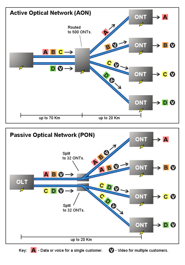
The following provides a comparison of the advantages and disadvantages of “actively switched” and “passively split” fiber optic communications technologies.
ACTIVE OPTICAL NETWORK (AON)
AON’s utilize intelligent switching and routing to direct and manage data flow within a network. The emergence of the Ethernet architecture, protocols and topologies in the transportation and the Intelligent Transportation systems (ITS) arena occurred around 1999, and is rooted in traditional, switched Ethernet networks that date back over 35 years.
Advantages
- Active Optical Networks have been successfully utilized for Transportation and ITS networks for more than 10 years, and currently represent the industry standard.
- AON’s provide a framework and architecture that enables physical route redundancies, which provides protection against fiber cuts and enables optimized data management strategies.
- Adding new devices to AON networks is simple “plug and play”, with little-to-no network reconfiguration required.
- AON’s provide the ability to deploy equipment and protocols that are standardized within the telecommunications industry.
- AON hardware is ubiquitous, with plenty of hardware vendors available, thus minimizing specific hardware/software/vendor dependencies.
- An AON ring architecture allows for simplified network reconfiguration, implementation of additional “head-ends”, or the relocation of head-end by simply connecting to the nearest point on the nearest ring.
- AON’s are fully bi-directional with equal upstream and downstream transmission rates.
Disadvantages
- Edge switches cost more than PON cabinet devices Optical Network Terminals (ONTs).
- Fully redundant core switch with optics cost more than the fully redundant PON’s OLT’s.
- Requires the installation of additional conduit and cable runs to achieve physical redundancies.
PASSIVE OPTICAL NETWORK (PON)
PON’s are a relatively new technology that has emerged from the telecoms and cable industry, most notably as a result of the surging demand for consumer-driven, high-bandwidth applications for the residential market. Due to the required data payloads, including voice, video and data, the communications providers realized a need for maximizing the use of each and every single fiber deployed in their network. Gigabit PON or GPON is an asymmetrical, “shared” bandwidth configuration with a maximum downstream bandwidth of 2.4Gbps and an upstream total bandwidth of 1.2Gbps per fiber.
Advantages
- Edge devices (cabinet transceivers or ONTs) are less expensive than typical Ethernet edge switches.
- PON’s utilize multiplexing (mux) technologies that enable multiple channels (typically 32 or 64) to utilize a single fiber.
- Due to the multiplexing architecture, the PON allows for the mux of 32 individual channels per single fiber, enabling communications to 32 different devices over the single mux’d fiber.
Disadvantages
- Due to the Point-to-Point architecture of PONs, the technology is unable to feasibly implement physical network redundancies for communications routes.
- If a splitter goes offline(splitter failure or cabinet hit), or a break in a cable occurs between the splitter and the head-end OLT (TMC), then all devices downstream from the break and the splitter will go offline until repairs can be rendered. Splitters represent a significant Single Point of Failure (SPOF) – which network design typically tries to minimize.
- Due to the multiplexing nature of the data transmission, faults are difficult to identify/isolate/remedy.
- The nature of PONs requires that fiber be installed in a manner that does not provide as much flexibility for future network configurations. All fiber backbone radiates from a single point,
- The PON architecture does not allow for the implementation of typical Ethernet network management features/protocols associated with layer 3 (OSI) networking protocols.
- Passive Optical LAN architecture is not recognized by any of the North American or international standards bodies as being a standards-based architecture for the enterprise environment.
- PON’s asymmetrical framework (designed for delivering video/voice to the home) results in an architecture that provides more downstream bandwidth (2.4Gbps) than upstream bandwidth (1.2Gbps) – generally opposite of the needs related to a typical ITS installation, and thus an inefficient use of the technology. The potential downstream bandwidth (2.4 Gbps) will probably never be realized, nor required, where the upstream limitation of 1.2Gbps could potentially yield a constraint in some future installations.
- Because a defined group of ONT’s share an upstream path, there is a potential for the collision of data. To correct for this, the OLT allocates specific time slots for each ONT to transmit Its data back to the OLT. This works well with Telecommunications/cable company networks where a majority of the data payload demand is downstream. However, in an ITS environment, the opposite is true as the upstream demand is exponentially greater and more critical.
- No Power Over Ethernet (PoE) capabilities via ONT.
Sources and Resources
Passive Optical Networks
http://en.m.wikipedia.org/wiki/Passive_optical_network
